الخميس، 14 يوليو 2011
مشاريع الكترونية مختلفة كاملة الشرح
- Solar Power Circuits charge controllers, dark-on light, meters
- LED Circuits LED illumination, LED rainbow
- Amateur Radio and RF Circuits beacon keyer, smooth sidetone, antenna tuner
- Music and Audio Circuits reverb, tube amps, tube fuzz, tube phaser, panner
- Micro Power FM Broadcasting Circuits FM stereo, J-Pole antenna, FM10 mods, solar powered bug
- Pulse Width Modulator (PWM) Circuits motor speed controls, DC light dimmers
- Telephone Circuits phone tap
- Geiger Counter Circuits counter mods, numerical counter, probe rebuilding
- Video Circuits camera motor, miniature camera/TV
- Miscellaneous Circuitry:
- The Big-E Stereo Parabolic Microphone
- Ultra Low Power LCD Indicator
- 12V, 4-AA Cell Differential Temperature Charger
- Temperature Controlled NICD Charger
- Microprocessor RS-232 Reset
- TTL Pulse Reading Logic Probe
- Lightning Activated Camera Shutter Trigger
- Constant Temperature Circuit
- Fluorescent Magic Eye Tubes photos and pinouts


الأربعاء، 13 يوليو 2011
اللحام للقطع الالكترونية
Soldering is defined as "the joining of metals by a fusion of alloys which have relatively low melting points". In other words, you use a metal that has a low melting point to adhere the surfaces to be soldered together. Consider that soldering is more like gluing with molten metal, unlike welding where the base metals are actually melted and combined. Soldering is also a must have skill for all sorts of electrical and electronics work. It is also a skill that must be taught correctly and developed with practice.
This tutorial will cover the most common types of soldering required for electronics work. This includes soldering components to printed circuit boards and soldering a spliced wire joint.
Soldering components onto a PCB involves preparing the surface, placing the components, and then soldering the joint.
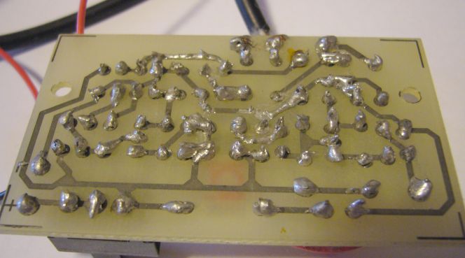
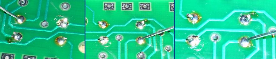
Cold joints can often be recognized by a characteristic grainy, dull gray colour, but this is not always the case. A cold joint can often appear as a ball of solder sitting on the pad and surrounding the component lead. Additionally you may notice cracks in the solder and the joint may even move. Below is the shocking image of every example of a bad solder joint you will ever see. It appears that this FM transmitter kit was assembled using the technique of "apply solder to iron then drip onto joint". If your joints are looking like this, then stop and practice after rereading this page. Note that not a single of of these joints is acceptable, but amazingly, the circuit worked.
 Most cold solder joints can be easily fixed. Generally all that is required is to reheat the joint and apply a little more solder. If there is already too much solder on the joint, then the joint will have to be desoldered and then soldered again. This is done by first removing the old solder with a desoldering tool or simply by heating it up and flicking it off with the iron. Once the old solder is off, you can resolder the joint, making sure to heat it thoroughly and keep it still as it cools.
This tutorial will cover the most common types of soldering required for electronics work. This includes soldering components to printed circuit boards and soldering a spliced wire joint.
Soldering Equipment
- The Soldering Iron/Gun
- The first thing you will need is a soldering iron, which is the heat source used to melt solder. Irons of the 15W to 30W range are good for most electronics/printed circuit board work. Anything higher in wattage and you risk damaging either the component or the board. If you intend to solder heavy components and thick wire, then you will want to invest in an iron of higher wattage (40W and above) or one of the large soldering guns. The main difference between an iron and a gun is that an iron is pencil shaped and designed with a pinpoint heat source for precise work, while a gun is in a familiar gun shape with a large high wattage tip heated by flowing electrical current directly through it.
For hobbyist electronics use, a soldering iron is generally the tool of choice as its small tip and low heat capacity is suited for printed circuit board work (such as assembling kits). A soldering gun is generally used in heavy duty soldering such as joining heavy gauge wires, soldering brackets to a chassis or stained glass work. You should choose a soldering iron with a 3-pronged grounding plug. The ground will help prevent stray voltage from collecting at the soldering tip and potentially damaging sensitive (such as CMOS) components. By their nature, soldering guns are quite "dirty" in this respect as the heat is generated by shorting a current (often AC) through the tip made of formed wire. Guns will have much less use in hobbyist electronics so if you have only one tool choice, an iron is what you want. For a beginner, a 15W to 30W range is the best but be aware that at the 15W end of that range, you may not have enough power to join wires or larger components. As your skill increases, a 40W iron is an excellent choice as it has the capacity for slightly larger jobs and makes joints very quickly. Be aware that it is often best to use a more powerful iron so that you don't need to spend a lot of time heating the joint, which can damage components.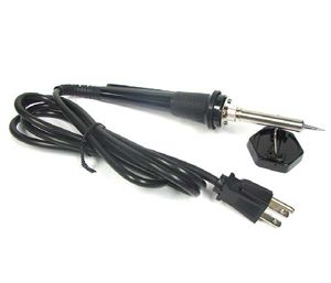
A 30W Watt Soldering Iron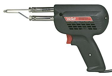
A 300W Soldering Gun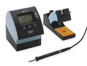 A variation of the basic gun or iron is the soldering station, where the soldering instrument is attached to a variable power supply. A soldering station can precisely control the temperature of the soldering tip unlike a standard gun or iron where the tip temperature will increase when idle and decrease when applying heat to a joint. However, the price of a soldering station is often ten to one hundred times the cost of a basic iron and thus really isn't an option for the hobby market. But if you plan to do very precise work, such as surface mount, or spend 8 hours a day behind a soldering iron, then you should consider a soldering station. The rest of this document will assume that you are using a soldering iron as that is what the majority of electronics work requires. The techniques for using a soldering gun are basically the same with the only difference being that heat is only generated when the trigger is pressed.
 - Solder
- The choice of solder is also important. There several kinds of solder available but only a few are suitable for electronics work. Most importantly, you will only use rosin core solder. Acid core solder is common in hardware stores and home improvement stores, but meant for soldering copper plumbing pipes and not electronic circuits. If acid core solder is used on electronics, the acid will destroy the traces on the printed circuit board and erode the component leads. It can also form a conductive layer leading to shorts.
For most printed circuit board work, a solder with a diameter of 0.75MM to 1.0MM is desirable. Thicker solder may be used and will allow you to solder larger joints more quickly, but will make soldering small joints difficult and increase the likelihood of creating solder bridges between closely spaced PCB pads. An alloy of 60/40 (60% tin, 40% lead) is used for most electronics work. These days, several lead-free solders are available as well. Kester "44" Rosin Core solder has been a staple of electronics for many years and continues to be available. It is available in several diameters and has a non-corrosive flux. Large joints, such as soldering a bracket to a chassis using a high wattage soldering gun, will require a separate application of brush on flux and a thick diameter solder of several millimeters. Remember that when soldering, the flux in the solder will release fumes as it is heated. These fumes are harmful to your eyes and lungs. Therefore, always work in a well ventilated area and avoid breathing the smoke created. Hot solder is also dangerous. It is surprisingly easy to splash hot solder onto yourself, which is a thoroughly unpleasant experience. Eye protection is also advised.
- Tinning The Soldering Tip
- Before use, a new soldering tip, or one that is very dirty, must be tinned. "Tinning" is the process of coating a soldering tip with a thin coat of solder. This aids in heat transfer between the tip and the component you are soldering, and also gives the solder a base from which to flow from.
- Step 1: Warm Up The Iron
- Warm up the soldering iron or gun thoroughly. Make sure that it has fully come to temperature because you are about to melt a lot of solder on it. This is especially important if the iron is new because it may have been packed with some kind of coating to prevent corrosion.
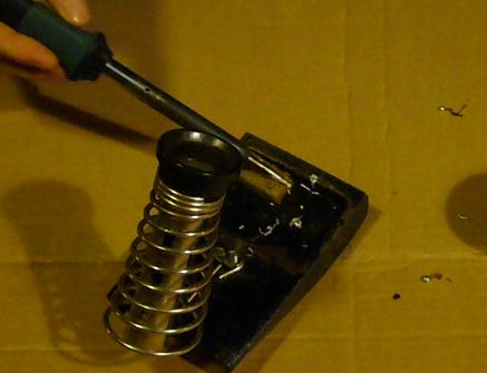
- Step 2: Prepare A Little Space
- While the soldering iron is warming up, prepare a little space to work. Moisten a little sponge and place it in the base of your soldering iron stand or in a dish close by. Lay down a piece of cardboard in case you drip solder (you probably will) and make sure you have room to work comfortably.
- Step 3: Thoroughly Coat The Tip In Solder
- Thoroughly coat the soldering tip in solder. It is very important to cover the entire tip. You will use a considerable amount of solder during this process and it will drip, so be ready. If you leave any part of the tip uncovered it will tend to collect flux residue and will not conduct heat very well, so run the solder up and down the tip and completely around it to totally cover it in molten solder.
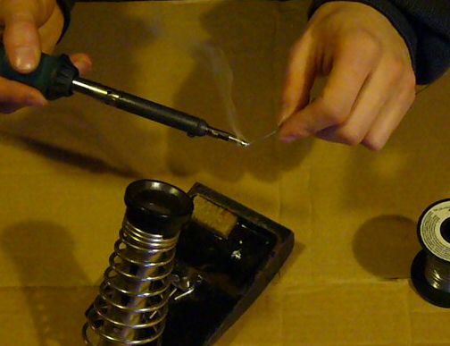
- Step 4: Clean The Soldering Tip
- After you are certain that the tip is totally coated in solder, wipe the tip off on the wet sponge to remove all the flux residue. Do this immediately so there is no time for the flux to dry out and solidify.
- Step 5: You're Done!
- You have just tinned your soldering tip. This must be done anytime you replace the tip or clean it so that the iron maintains good heat transfer. You can also watch the tinning process on video below (requires Flash):
Preparing To Solder
Soldering A Printed Circuit Board (PCB)
Soldering a PCB is probably the most common soldering task an electronics hobbyist will perform. The basic techniques are fairly easy to grasp but it is a skill that will take a little practice to master. The best way to practice is to buy a simple electronics kit or assemble a simple circuit (such as an LED chaser) on a perf-board. Don't buy that expensive kit or dive into a huge project after only soldering a few joints.Soldering components onto a PCB involves preparing the surface, placing the components, and then soldering the joint.
- Step 1: Surface Preparation:
- A clean surface is very important if you want a strong, low resistance solder joint. All surfaces to be soldered should be cleaned well. 3M Scotch Brite pads purchased from the home improvement, industrial supply store or automotive body shop are a good choice as they will quickly remove surface tarnish but will not abrade the PCB material. Note that you will want industrial pads and not the kitchen cleaning pads impregnated with cleaner/soap. If you have particularly tough deposits on your board, then a fine grade of steel wool is acceptable but be very cautious on boards with tight tolerances as the fine steel shavings can lodge between pads and in holes. Once you have cleaned the board down to shiny copper you can use a solvent such as acetone to clean any bits of the cleaning pad that may remain and to remove chemical contamination from the surface of the board. Methyl hydrate is another good solvent and a bit less stinky then acetone. Be aware that both these solvents can remove ink, so if your board is silk screened, test the chemicals first before hosing down the entire board. A few blasts with compressed air will dry out the board and remove any junk that may have built up in the holes. It also never hurts to give the component leads a quick wipe down as well, to remove glue or tarnish that may have built up over time.
- Step 2: Component Placement
- After the component and board have been cleaned, you are ready to place the components onto the board. Unless your circuit is simple and only contains a few components, you will probably not be placing all the components onto the board and soldering them at once. Most likely you will be soldering a few components at a time before turning the board over and placing more. In general it is best to start with the smallest and flattest components (resistors, ICs, signal diodes, etc.) and then work up to the larger components (capacitors, power transistors, transformers) after the small parts are done. This keeps the board relatively flat, making it more stable during soldering. It is also best to save sensitive components (MOSFETs, non-socketed ICs) until the end to lessen the chance of damaging them during assembly of the rest of the circuit. Bend the leads as necessary and insert the component through the proper holes on the board. To hold the part in place while you are soldering, you may want to bend the leads on the bottom of the board at a 45 degree angle. This works well for parts with long leads such as resistors. Components with short leads such as IC sockets can be held in place with a little masking tape or you can bend the leads down to clamp onto the PC board pads. In the image below, a resistor is ready to solder and is held in place by slightly bent leads.
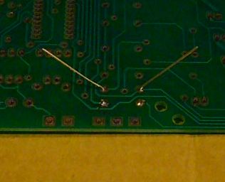
- Step 3: Apply Heat
- Apply a very small amount of solder to the tip of the iron. This helps conduct the heat to the component and board, but it is not the solder that will make up the joint. To heat the joint you will lay the tip of the iron so that it rests against both the component lead and the board. It is critical that you heat the lead and the board, otherwise the solder will simply pool and refuse to stick to the unheated item. The small amount of solder you applied to the tip before heating the joint will help make contact between the board and the lead. It normally takes a second or two to get the joint hot enough to solder, but larger components and thicker pads/traces will absorb more heat and can increase this time. If you see the area under the pad starting to bubble, stop heating and remove the soldering iron because you are overheating the pad and it is in danger of lifting. Let it cool, then carefully heat it again for much less time.
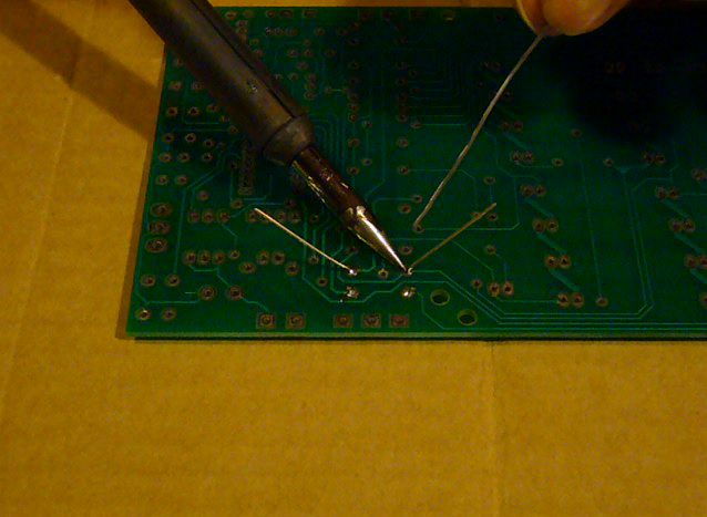
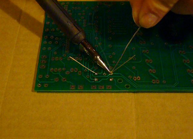
- Step 4: Apply Solder To The Joint
- Once the component lead and solder pad has heated up, you are ready to apply solder. Touch the tip of the strand of solder to the component lead and solder pad, but not the tip of the iron. If everything is hot enough, the solder should flow freely around the lead and pad. You will see the flux melt liquify as well, bubble around the joint (this is part of its cleaning action), flow out and release smoke. Continue to add solder to the joint until the pad is completely coated and the solder forms a small mound with slightly concave sides. If it starts to ball up, you have used too much solder or the pad on the board is not hot enough.
Once the surface of the pad is completely coated, you can stop adding solder and remove the soldering iron (in that order). Don't move the joint for a few seconds as the solder needs time to cool and resolidify. If you do move the joint, you will get what's called a "cold joint". This is recognized by it's characteristic dull and grainy appearance. Many cold joints can be fixed by reheating and applying a small amount of solder, then being allowed to cool without being disturbed.
- Step 5: Inspect The Joint and Cleanup
- Once the joint is made you should inspect it. Check for cold joints (described a little above and at length below), shorts with adjacent pads or poor flow. If the joint checks out, move on to the next. To trim the lead, use a small set of side cutters and cut at the top of the solder joint.
After you have made all the solder joints, it is good practice to clean all the excess flux residue from the board. Some fluxes are hydroscopic (they absorb water) and can slowly absorb enough water to become slightly conductive. This can be a significant issue in a hostile environment such as an automotive application. Most fluxes will clean up easily using methyl hydrate and a rag but some will require a stronger solvent. Use the appropriate solvent to remove the flux, then blow the board dry with compressed air.
- See It On Video
- You can watch several joints being soldered in the video below.
- Conformal Coatings
- If the printed circuit board you just soldered is going to be used in a hostile environment where it is subjected to moisture, dirt or chemicals, it may be a good idea to apply a conformal coating such as those made by MG Chemicals. These coatings are sprayed onto a PC board to seal it against hazards of the environment. Coatings are usually lacquer, silicone or urethane based and are applied to both sides of the board once it is fully assembled and tested.
Cold Solder Joints
A "cold solder joint" can occur when not enough heat is applied to the component, board, or both. Another common cause is a component moving before the solder has completely cooled and solidified. A cold joint is brittle and prone to physical failure. It is also generally a very high resistance connection which can effect the operation of the circuit or cause it to fail completely.Cold joints can often be recognized by a characteristic grainy, dull gray colour, but this is not always the case. A cold joint can often appear as a ball of solder sitting on the pad and surrounding the component lead. Additionally you may notice cracks in the solder and the joint may even move. Below is the shocking image of every example of a bad solder joint you will ever see. It appears that this FM transmitter kit was assembled using the technique of "apply solder to iron then drip onto joint". If your joints are looking like this, then stop and practice after rereading this page. Note that not a single of of these joints is acceptable, but amazingly, the circuit worked.
Soldering A Wire Joint or Splice
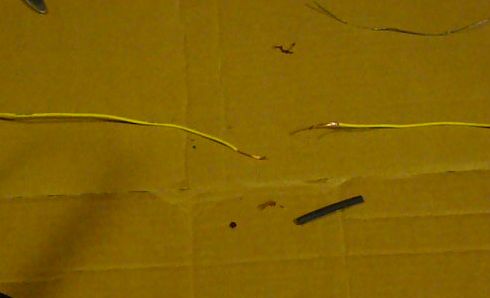
Another very common task is soldering a joint between two or more wires. Unlike soldering a PCB where the component is generally held only by the solder joint itself, a splice between wires must be physically strong before it is soldered. This usually means twisting the wires together properly and then soldering. Areas where you will see soldered wire joints are cable repairs and automotive wiring. In these cases, the joint must be insulated after soldering as well.- Step 1: Strip The Wires To Be Joined, Slip On Insulation
- Heat shrink tubing is generally the preferred method to insulate a wire splice. There are two main types of heat shrink available; adhesive lined and non-adhesive lined. Non-adhesive tubing forms an insulating barrier only and thus is suitable for use only when the joint will not be subjected to moisture, chemicals or other harsh environments. Adhesive lined heatshrink tubing is lined with a heat sensitive adhesive that melts to seal the joint as the tubing is heated. Thus it forms a totally sealed joint and is used when a splice will be subjected to moisture or other elements which can effect the joint. As an example, you would use non-adhesive shrink tube when repairing a lamp cord, but you would use adhesive lined tubing when installing a car stereo. Use heat shrink tube with a diameter of approximately 1.5 times to two times the diameter of the wires to be joined. Cut the tube to length so that it will extend past each side of the joint by at least 0.5 inches and then slip it over one of the wire ends. Now strip about an inch of insulation from each wire end. If you are joining rather thick wire (thicker then 12 gauge) then you may want to strip a little more insulation to make twisting the wire easier.
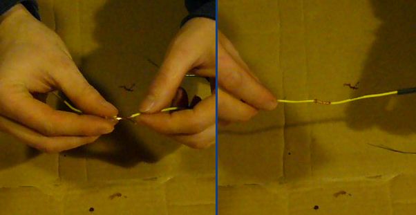
- Step 2: Twist The Wires Together
- A strong mechanical connection is necessary before the wires are to be soldered so you must twist them together. The wires will be twisted in what is referred to as a "Lineman's joint" where the wires are joined in a straight line as opposed to twisting together in a "V" shape. Hold the stripped ends of the wires together in an "X" shape so their middles cross one another and then twist one of the wires along the other wires length. Then twist the other side to match. What you will end up with is a strong wire joint that is generally not much thicker then the wire itself.
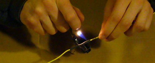
- Step 3: Apply Heat
- Apply your heat to the bottom of the wire joint and use the thicker section of the soldering tip. If you heat up the top of the wire, you will get a lot of heat loss since heat rises. The thicker area of the solder iron tip will conduct more heat into the wire joint. It also helps to slightly wet the tip of the soldering iron to further aid in heat transfer. The thicker the wire joint, the more heat will be required. Be careful, because on thin wires with cheap insulation you can actually melt quite a bit of it off if you overheat the joint. Once the joint is hot enough (a good clue is when the solder you used to wet the tip of the iron flows into the joint) you can move on to applying solder.
Once you have soldered a number of these joints you will be able to judge how much heat must be applied based on the thickness of the wire.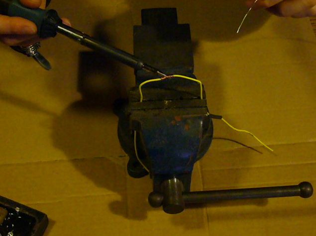
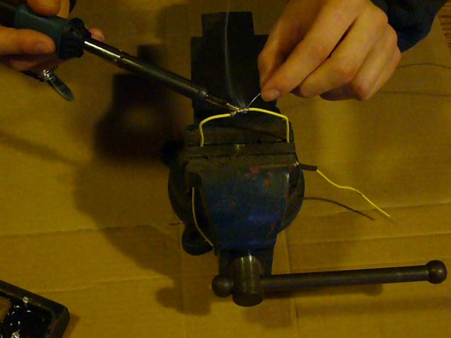
- Step 4: Apply Solder To The Joint
- With the joint fully heated, apply your solder to the joint just above the soldering tip. If it doesn't begin to melt immediately then you will need more heat. Once the solder begins to melt it will flow into the joint around the soldering iron. As the solder flows, move the tip along the wire joint while applying solder. The joint should start to suck in the solder as it is applied. If you find that the solder is pooling where it is touched to the joint yet it is not flowing inside, you will need more heat. Continue adding solder until the joint is fully covered. You should still be able to see the outlines of the individual wire strands but no copper of the wire should be visible. If you add too much solder to the point where the joint becomes a blob, you will end up with a brittle joint and the excess solder will need to be removed.
- Step 5: Clean The Flux
- If the wire joint is to be sealed or used in an area it will be exposed to moisture, the flux must be removed. Some fluxes will absorb moisture or other chemicals and become corrosive to the joint. While there are flux removal chemicals available most fluxes can be cleaned up using methyl hydrate available at any hardware store. Some are even water soluble.
- Step 6: Insulate The Joint
- Slide the heat shrink tubing so that it evenly covers the joint and apply heat to shrink it. Ideally, you will want a heat gun for this but a simple lighter is acceptable as long as you keep the flame moving to avoid burning the tubing or the wire. If you used adhesive lined heat shrink, you need to heat the tube until it has shrunk fully around the wire and a little of the adhesive has oozed out the ends. Non-lined heatshrink can be heated until it tightly covers the joint. You can overheat this stuff. If too much heat is used, then the insulation underneath will begin to break down and may form a bubble. A bubble could also be caused if you heat adhesive lined tubing to the point where it starts to boil.
- You're Done! Now Just Watch The Video
- That's it! Your wire joint is now complete. You can watch the process on video below:
Tips and Tricks
Soldering is something that needs to be practiced. These tips should help you become successful so you can stop practicing and get down to some serious building.- Use heatsinks. Heatsinks are a must for the leads of sensitive components such as ICs and transistors. If you don't have a clip on heatsink, then a pair of pliers is a good substitute.
- Keep the iron tip clean. A clean iron tip means better heat conduction and a better joint. Use a wet sponge to clean the tip between joints. Keep the tip well tinned.
- Double check joints. When assembling complicated circuits, it is good practice to check joints after soldering them. Use a magnifying glass to visually inspect the joint and a meter to check resistance.
- Solder small parts first. Solder resistors, jumper leads, diodes and any other small parts before you solder larger parts like capacitors and transistors. This makes assembly much easier.
- Install sensitive components last. Install CMOS ICs, MOSFETs and other static sensitive components last to avoid damaging them during assembly of other parts.
- Use adequate ventilation. Most soldering fluxes should not be breathed in. Avoid breathing the smoke created and make sure that the area you are working in has adequate airflow to prevent buildup of noxious fumes.
Soldering Safety
While soldering is not generally a hazardous activity, there are a few things to keep in mind. The first and most obvious is that it involves high temperatures. Soldering irons are going to be 350F or higher, and will cause burns very quickly. Make sure to use a stand to support the iron and keep the cord away high traffic areas. Solder itself can drip, so it makes sense to avoid soldering over exposed body parts. Always work in a well lit area where you have space to lay parts out and move around. Avoid soldering with your face directly above the joint because fumes from the flux and other coatings will irritate your respiratory tract and eyes. Most solders contain lead, so you should avoid touching your face while working with solder and always wash your hands before eating.برنامج يوضح الرموز الالكترونية
Schematic Symbol Reference
This is an offline version of the Schematic Symbol Reference. It contains all the same info, but is a standalone program that requires no Internet connection to run. This will run under Windows 95, Windows 98 and NT4 Server and Workstation.
If you have the files
MSVBVM50.DLL and MSVBVM60.DLL in your windows\sytem directory, then you can download the compact version (917K). Otherwise, you will need to download the full version (2.7MB). ادوات قياس القطع الالكترونية online
Online 555 Calculator
This tool use to calculate any parameter of 555 timer IC.
Standard resistance values calculator
This is EIA standard resistance value calculator
Serie and Parallel resistor closest calculator
This is a tool which to be used to combine of two resistors in series or parallel to gives a match better than the closest standard value, for the E12(10%) and E24(5%) series
Single layer coil inductance calculator
The inductance calculator for Single layer air coil inductor
Multilayer Air coil inductance calculator
The inductance calculator for multilayer air coil inductor
Other useful links
Resistor Color Code Calculator
LM317 Calculator
LED Calculator
الاشتراك في:
الرسائل (Atom)